Zones and conduits (with protection needs analysis)
What is a zone?
A complete plant is difficult to grasp or categorize in terms of possible threats and necessary security measures. For this reason, the IEC 62443 standard divides a complete system into so-called zones. In terms of the standard, a zone can be a physical and/or logical group of system components to which the same security requirements apply.
Zones are useful to consider critical components separately and thus to isolate them from the overall system. This way, a segmentation of the network takes place, whereby individual zones can be shielded from the "outside world", e.g. by firewalls. In addition to this shielding, it is recommended to additionally harden individual components and subsystems.
What is the demilitarized zone (DMZ)?
The so-called demilitarized zone (DMZ) plays a central role. It acts like a "buffer zone" between the public network (Internet) and the internal ICS network thus decoupling them. Any communication between the external and internal networks must pass the DMZ which strictly controls the information flow: When accessing the DMZ from outside the ICS, communication connections are only possible to explicitly permitted components such as authentication servers, application gateways or webservers. By restricting external access to these appropriately configured components in the DMZ, other ICS-internal components remain invisible from outside. Thus the ICS network is protected from attacks from public networks.
This information flow control is usually realized by one or several DMZ firewalls.
What is a conduit?
Zones communicate with each other or/and with external networks. The IEC 62443 standard designates the technical means of communication and/or controlling the communication flow between zones as conduits. Consequently, a conduit is a logical grouping of cyber assets dedicated exclusively to communications between two or more zones, and which share the same cybersecurity requirements.
A conduit may consist of a single service (e.g., an Ethernet network) or multiple data carriers. Thus conduits control the access to a zone and they must secure the integrity of the network traffic thus providing protection to the zone.
Conduits must control the information flow and they should separate the ICS from public networks
According to the standard, a conduit may cross a zone as long as the cyber security of the channels running in the conduit cannot be compromised by the zone.
Security level (SL) of zones and conduits
For each zone/conduit, a security level (SL) has to be determined depending on its protection needs. By means of their SL, zones and conduits can be compared to each other with respect to their security capability. The SL can be considered as the zone's/conduit's qualitative degree of security.
To each zone/conduit, a target SL (SL-T) should be assigned. This is the SL, the zone/conduit must achieve according to your risk assessment. After having implemented the required security measures, the resulting SL-A of the zone/conduit can be determined. SL-A is the level, this zone/conduit actually achieves with the taken measures.
A detailed description of the following example is contained in the section Threat-Risk-Assessment.
The division into zones and conduits supports the Defense-in-Depth concept according to the IEC 62443 standard.
Threat-risk-assessment for zones and conduits
Each security-related consideration has to start with a threat-risk-assessment. Actually, a first threat and risk analysis is needed to initially determine the layout of the zones and conduits.
As part of such an analysis, you must identify zones and conduits that require protection, classify the data stored/processed in and transmitted between these zones, identify potential threats, and determine vulnerabilities. Based on these values, you determine the protection needs and finally develop a protection concept.
In the following, you will find an exemplary description of how to proceed with the threat-risk-assessment. The example shown above of a division into zones and conduits is used as a concrete basis for this procedure.
- Segmentation: available zones
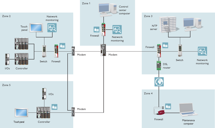
In the example figure shown above, a plant has been divided into 5 zones:
- Zone 1: Control center (SCADA).
- Zone 2: Main process zone, which we will look at as an example in this context. See description below this list.
- Zone 3: Management zone.
- Zone 4: Sub-process zone.
- Zone 5: Remote maintenance zone.
We will look at zone 2 as an example in this context. Its function is to collect and process data from the process and the sub-process. It consists of a network monitoring (no. 1 in the figure), PLCnext Technology controllers each with I/O devices connected to the field bus (2), a WebPanel for controlling and visualization purposes (3), and an Ethernet switch (4). A firewall (5) handles the communication with the other zones (conduits).
- Data identification
Based on this zone definition, the data worthy of protection must be identified which are
1. stored/processed within each zone, and
2. transmitted between zones via the identified conduits.Further Information: Refer to the topic Data Classification & Protection Needs for an overview on data classes.In the example, the following data is relevant in zone 2:
- Configuration data (CD) stored on the devices used to build automation infrastructures and systems.
- Log data onboard (LO) stored on the devices involved.
- Application data (AD) on the devices involved.
- Process data (PD) which are transferred between and processed by the devices.
- System data (SD) such as access credentials, keys and certificates stored on the devices.
- Data classification: protection need analysis
Based on the identified data classes, the protection needs can be determined. This classification is made under three aspects:
- A = Availability
- I = Integrity
- C = Confidentiality
Further Information: Refer to the topic Data Classification & Protection Needs for an overview on protection classes.In our example zone 2, the following protection needs have been identified (excerpt from all classes):
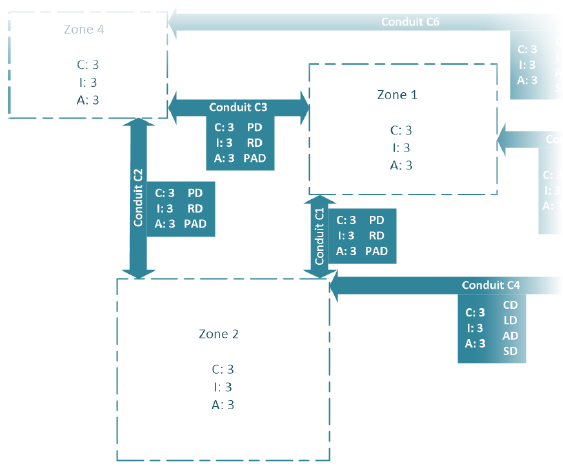
Data class Objective: Protection need Justification Application Data (AD) Availability: 3 System cannot start or stop. Shared Libs are on the SD card and can no longer be loaded. Integrity: 3 The loss of integrity can result in high damage. Confidentiality: 2 Know-how protection. Necessary but not mandatory. Process Data (PD) Availability: 3 Process data are mandatory for the plant. Integrity: 3 Corrupted process data may cause high damage. Confidentiality: 1 Not interpretable by uninvolved parties or interpretable only with high effort. 90% of applications do not require confidentiality of process data. Performance is more important. System Data (SD), in particular private keys and user credentials Availability: 2 Failure/expiration of system data only leads to failure of e.g., remote access capabilities while the process continues to run. Integrity: 3 Intentional or unintentional falsification of system data can cause medium damage (failure of a component or system part). Confidentiality: 4 Highly sensible data. - Zone classification
Based on the data classification, the protection needs of each zone can be determined. The maximum principle applies, i.e. the highest protection need of a data class must apply to the entire zone (in each case for A/I/C).
In our example, the following values have been determined for zone 2 (main process):- Protection need A for zone 2 = 3
- Protection need I for zone 2 = 3
- Protection need C for zone 2 = 3
- Conduit classification
For the necessary communication channels between the previously defined zones and conduits must be identified. In the same way as for the zones, the data transmitted via each conduit must be classified and their protection need (A/I/C) must be determined.
Example: determined protection needs as schematic representationFor our example plant, finally the following schematic representation results which shows the zones, conduits as well as the classified data with their protection needs:
- Specification of protective measures
Based on the evaluations in the steps 1 to 4, you can now specify the protection measures.
A protection need of 3 (A/I/C) for zone 2, for example, can be fulfilled by- segmentation of the network
- the connection of the main process in zone 2 to the system via a ring topology to increase availability
- encrypted communication with other zones
- firewalls, routing & VPN for securing the interfaces outside the zone boundaries
- hardening measures of the devices in the zone, such as deactivation of unused device interfaces
- implementing an Intrusion Detection System which monitors all data flows and generates an alarm in case of an unknown participant or an unusually high data transfer volume
- installation of uninterruptible power supplies (UPS)
- implementing protection measures regarding the environment of the plant (access control, lockable rooms and cabinets, installation of a fire alarm system, monitoring of the room climate
- sensitization and training of employees on the subject of information security
In particular for zone 2 which contains a PLCnext Technology controller with periphery, the following measures are suitable:
- SSH (certificates, user credentials) for securing Configuration Data and System Data.
- HTTPS and user credentials for securing the communication with the Web-Based Management (WBM) of the controller.
- TLS and user credentials secure the Log Data and Application Data transfer.
- HTTPS and user credentials and cryptographic strong token for securing eHMI.
- TPM (supplier root of trust) for secure storage of user credentials, keys, certificates (System Data).
- Certificates secure the OPC UA communication.
- After having implemented suitable security mechanisms (in accordance with the results of your assessment), the residual risk should be determined.