AXC F 2152
The Security Profile must be activated, the left-alignable Ethernet module must be installed and the corresponding bus base module must be used.
For further information about the left-alignable Ethernet module (item no. 2403115), refer to the respective product documentation:
Connecting and operating elements of the controller
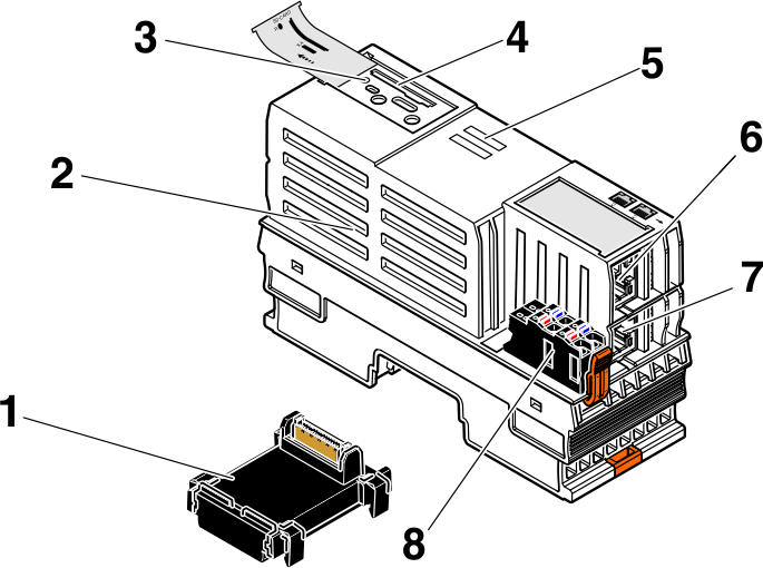
The controller consists of the following components:
| 1 | Bus base module Note: To be able to use the AXC F 2152 with the extension module AXC F XT ETH 1TX, you need the bus base module AXC BS L 2, item no. 1064312. |
| 2 | Electronics module |
| 3 | Reset button |
| 4 | SD card holder |
| 5 | Diagnostic and status indicators |
| 6 | Ethernet interface X2 |
| 7 | Ethernet interface X1 |
| 8 | Supply connector (connector for connecting the supply voltage (communications voltage UL)) |
SD card
- Only use encrypted SD cards!
Information on this can be found in the topic SD card encryption.
Components of the left-alignable Ethernet module
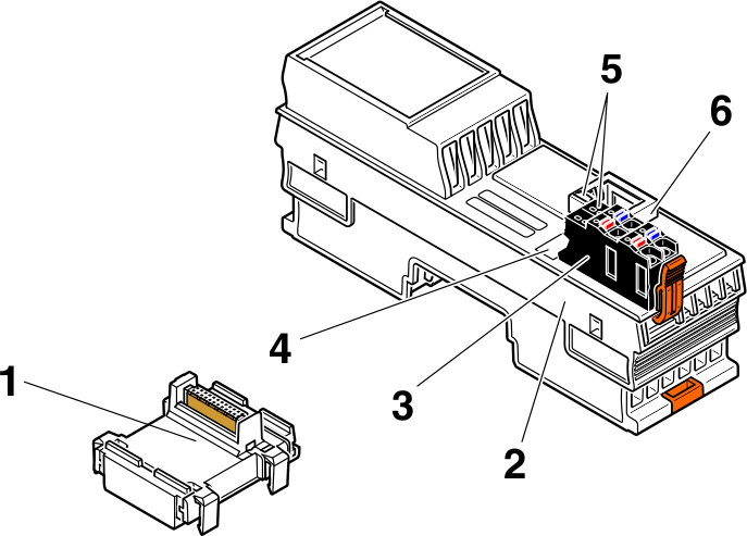
The left-alignable Ethernet module consists of the following components:
| 1 | Bus base module |
| 2 | Electronics module |
| 3 | Supply connector |
| 4 | Function identification |
| 5 | Diagnostic and status indicators |
| 6 | Ethernet interface |
Security seals
In order to prevent manipulation of the device supplied and to detect unauthorized opening of the device, security seals have been applied to the controller.
From production dates Q2/2022 and later, the housing of PLCnext Control AXC F 2152 is protected by a security seal on both sides like shown below.
These security seals are damaged in the event of unauthorized opening. In this case, correct operation of the PLCnext Control can no longer be ensured.
- Check the delivery for transport damage. Damaged packaging is an indicator of potential damage to the device that may have occurred during transport. This could result in a malfunction.
- Do not open the housing. If the housing is opened, the function of the device can no longer be ensured.
- Check at regular intervals that none of the seals are damaged. If any of the seals are damaged or missing, it may be that the device has been tampered. In this case, contact Phoenix Contact without delay before using the device.

1 Security seals
Assignment of the Ethernet interfaces
The following is an overview of how the Ethernet interfaces are assigned on the various pages in the WBM:
| Ethernet interface hardware | Ethernet interface WBM - Network page | Ethernet interfaces WBM - Firewall page |
| AXC F 2152: X2 | TCP/IP (LAN1) - Switched Mode (see Assigning IP addresses) |
eth0 (see Configuring extended firewall settings) |
| AXC F 2152: X1 | TCP/IP (LAN1) - Switched Mode (see Assigning IP addresses) |
eth0 (see Configuring extended firewall settings) |
| AXC F XT ETH 1TX (left-alignable Ethernet module) |
TCP/IP (EXT LAN 1) (see Assigning IP addresses) |
enp1s0 (see Configuring extended firewall settings) |
Activating PROFINET
After you have performed a threat analysis and implemented appropriate protective measures from the security context, you can activate PROFINET.
![]() For information on how to activate PROFINET, refer to the topic Activating PROFINET in this PLCnext Technology ‑ Security Info Center.
For information on how to activate PROFINET, refer to the topic Activating PROFINET in this PLCnext Technology ‑ Security Info Center.
![]() For further information on PROFINET in the WBM, refer to the PROFINET diagnostics topic in the main PLCnext Technology ‑ Info Center.
For further information on PROFINET in the WBM, refer to the PROFINET diagnostics topic in the main PLCnext Technology ‑ Info Center.
Using PROFINET
PROFINET is always operated on the extension module, while PLCnext Control is responsible for network segmentation. This results in the following architecture:
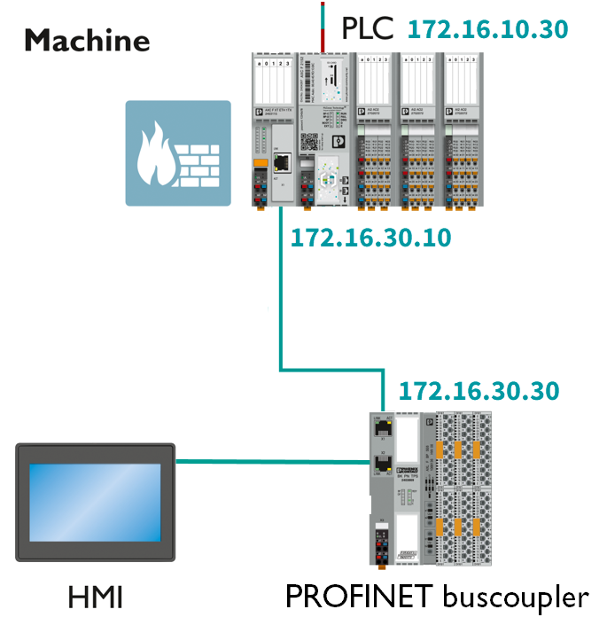
Accordingly, you need to adjust the firewall configurations (for more information, refer to the firewall basic configurations ):


How to reset the controller
Reset 1
Resetting the controller to default setting type 1 deletes all settings that you have configured. These include, for example:
- The PLCnext Engineer project, including all applications that have been programmed in accordance with IEC 61131-3
- All applications that were programmed using high-level languages
- The configured bus configuration
- The network configuration of the controller
- Changes and extensions that you have made to the operating system or to the firmware
To reset the controller to default setting type 1, proceed as follows:
- Switch off the supply voltage of the controller.
- After the LEDs have gone out, press the reset button.
- Hold the reset button down and switch the supply voltage on.
The RUN and FAIL LEDs light up. - Release the reset button.
The controller is reset to default setting type 1.
Reset 2
Resetting to default setting type 2 resets the controller to the delivery state. This deletes all settings that you have configured.
To reset the controller to default setting type 2, proceed as follows:
- Switch off the supply voltage of the controller.
- After the LEDs have gone out, press the reset button.
- Hold the reset button down and switch the supply voltage on.
The RUN and FAIL LEDs light up. - Press and hold the Reset button down (approx. 30 s) until all LEDs (except the E and D LEDs) light up.
- Release the reset button.
The controller is reset to default setting type 2.
Netload Limiter configuration
You configure the Netload Limiter on the Netload Limiter page in the WBM (Configuration → Network, Netload Limiter tab).
The Netload Limiter must be configured on the interface of the left-alignable Ethernet module (TCP/IP (EXT LAN 1)).
For further information, refer to the topic Configuring Netload Limiter.
Controller-specific information on the 62443-4-2 compliance list