BPC 9102S
Connecting and operating elements
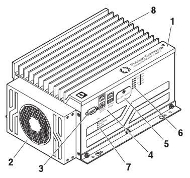
| 1 | BPC 9102S |
| 2 | BPC 9102 FAN KIT (optional) |
| 3 | COM service interface (D-SUB 9 pin strip) |
| 4 | LAN1/LAN2/LAN3 Ethernet interfaces (RJ45 jacks; 10/100/1000 Mbps) and USB service interface (USB 3.0 type A socket) |
| 5 | Cover of the SD card holder (slot for the configuration memory) and MRESET button |
| 6 | Diagnostics and status indicators (LED) |
| 7 | Status LEDs of the device-internal UPS |
| 8 | Connection for external supply voltage (24 V DC) |
Security seals
In order to prevent manipulation of the device supplied and to detect unauthorized opening of the device, security seals have been applied to the BPC 9102S.
These security seals are damaged in the event of unauthorized opening. In this case, correct operation of the PLCnext Control can no longer be ensured.
- Check the delivery for transport damage. Damaged packaging is an indicator of potential damage to the device that may have occurred during transport. This could result in a malfunction.
- Do not open the housing. If the housing is opened, the function of the device can no longer be ensured.
- Check at regular intervals that none of the seals are damaged. If any of the seals are damaged or missing, it may be that the device has been tampered. In this case, contact Phoenix Contact without delay before using the device.

| 1 | Security seals (on the unillustrated side of the BPC 9102S) |
USB and COM service interfaces
The BPC 9102S has a USB service interface (USB 3.0 type A socket) and a COM service interface (D-SUB 9 pin strip). These two interfaces are for internal service purposes only. During normal operation of the device, these interfaces cannot be used.
Diagnostics and status indicators

| LED | Color | Meaning | Status | Description |
| Run-S | Green | Operating state of the safe application program | On | Cyclical processing of the safety-related application program has started. |
| Off | Cyclical processing of the safety-related application program has stopped. | |||
| FS-S | Red | Failure state: Safe state of the SPLC 3000 | On | A critical error has occurred and been detected. The SPLC 3000 has switched to the safe state (failure state). |
| Flashing (1 Hz) | This can indicate:
|
|||
| Off | Error-free operating state of the SPLC 3000 with supply voltage present |
SD card
The use of the SD card is mandatory. You may only use encrypted SD cards (refer to the topic SD card encryption).
Phoenix Contact recommends the use of the following SD cards:
- SD FLASH 16GB PLCNEXT MEM LIC (item no. 1831737)
- SD FLASH 32GB PLCNEXT MEMORY LIC (item no. 1151111)
- SD FLASH PLCNEXT MEMORY LIC CFG (item no. 1308064)
- SD FLASH 8GB PLCNEXT MEMORY LIC (item no. 1151112) - discontinued
From firmware 2024.0 LTS, these special SD cards provide data protection, and therefore can be used together with the Security Profile.
Sensitive data is stored on the SD card. This data can even be restored after reformatting the SD card.
- To protect the data, make sure that the cover of the slot for the SD card is always screwed tight.
Assignment of the Ethernet interfaces

The BPC 9102S is equipped with the following interfaces:
| Pos. | Interfaces | Description | |
| 1 | COM | RS-232 | Service interface (reserved internally): D-SUB 9 pin strip (serial, RS-232) |
| 2 | LAN1 | 3 x Ethernet | Ethernet: 1 Gbps or 2.5 Gbps |
| LAN2 | PROFINET: Controller interfaces function (max. 1 Gbps) |
||
| LAN3 | PROFINET: Device interfaces function (max. 1 Gbps) |
||
| 3 | USB | Service interface (reserved internally): USB 3.0 socket (type A) |
|
The following is an overview of how the Ethernet interfaces are assigned by default in the various pages in the WBM:
| Ethernet interface hardware | Description | PROFINET function by default | Ethernet interface WBM - Network page | Ethernet interfaces WBM - Firewall page |
| X2:LAN1 | 10/100/1000 BASE-T(X), separate MAC address |
|
TCP/IP (LAN1) | LAN1 |
| X3:LAN2 | 10/100/1000 BASE-T(X), separate MAC address |
PROFINET Controller | TCP/IP (LAN2) | LAN2 |
| X4:LAN3 | 10/100/1000 BASE-T(X), common MAC address, internally switched |
PROFINET Device | TCP/IP (LAN3) | LAN3 |
Activating PROFINET
After you have performed a threat analysis and implemented appropriate protective measures from the security context, you can activate PROFINET.
![]() For information on how to activate PROFINET, refer to the topic Activating PROFINET in this PLCnext Technology ‑ Security Info Center.
For information on how to activate PROFINET, refer to the topic Activating PROFINET in this PLCnext Technology ‑ Security Info Center.
![]() For further information on PROFINET in the WBM, refer to the PROFINET diagnostics topic in the main PLCnext Technology ‑ Info Center.
For further information on PROFINET in the WBM, refer to the PROFINET diagnostics topic in the main PLCnext Technology ‑ Info Center.
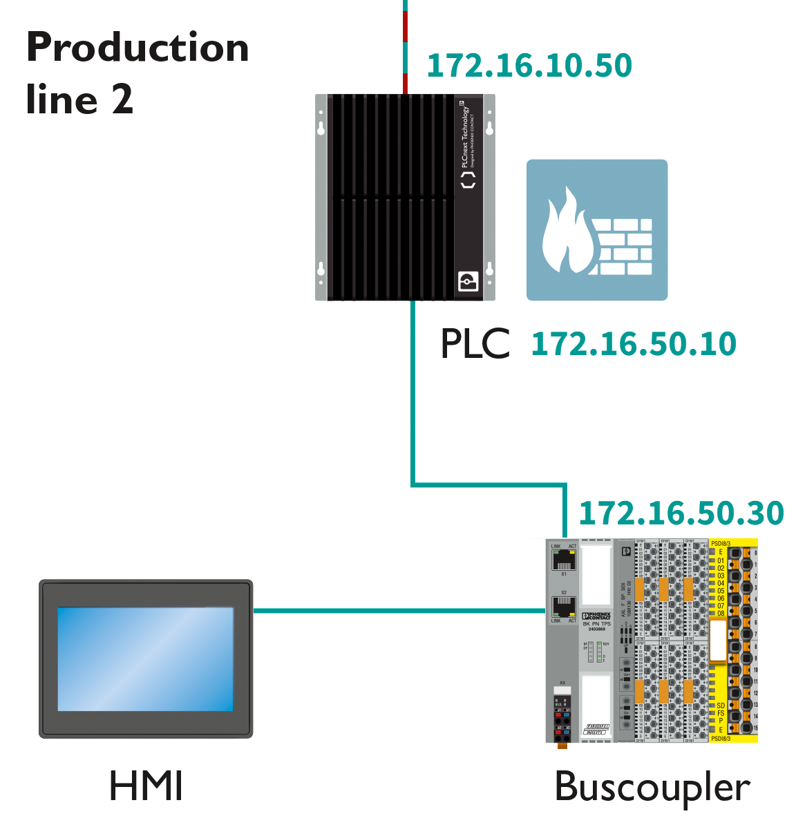
Using PROFINET
If you activate and use PROFINET , it is strongly recommended to use the PROFINET configuration described below.
Depending on the connected interface, the BPC 9102S can be accessed on the Ethernet via three different IP addresses.
- The IP addresses of interfaces LAN1/LAN2/LAN3 must be in different subnets.
- The PROFINET controller function of the BPC 9102S is available at interface LAN2. This interface must then be assigned an IP address if the PROFINET controller function of the device is to be used in the application.
- An IP address must be assigned to the LAN3 interface if you want to use the PROFINET device function of the BPC 9102S on these interfaces.
- The LAN1 and LAN3 interfaces do not necessarily have to be assigned an IP address if, for example, communication between a PC with PLCnext Engineer and the BPC 9102S is also implemented via the LAN2 interface. We recommend that appropriate IP addresses be assigned to all interfaces.
You need to adjust the firewall configurations (for more information, refer to the firewall basic configurations ):


Resetting the controller
You reset the BPC 9102S by actuating the MRESET button.
The MRESET button is located under the side cover of the BPC 9102S. The button can only be pressed with a pointed object (such as a pen).
Using the MRESET button will delete the application program in the BPC 9102S main memory and the retain data.
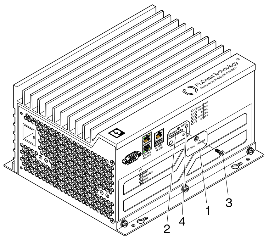
Procedure:
- To actuate the MRESET button (4), remove the screw (3) in the cover (1) with a Torx® TX 10 screwdriver.
- Then swivel the cover (1) to the side so that you can easily access the MRESET button (4).
- To delete the application program and the retain data, actuate the MRESET button in the following sequence:
- Press and hold down the button for three seconds.
- Release the button for less than three seconds.
- Press and hold down the button for three seconds.
- Re-affix the cover (1) after actuating the MRESET button by tightening the screw (3) to protect the MRESET button against accidental damage or actuation.
Secure disposal
Sensitive data is stored on the SD card. This data can even be restored after reformatting the SD card. To ensure that your data does not fall into unauthorized hands, you should physically destroy the SD card before disposal.
- Physically destroy the SD card, e.g., by cutting up the SD card.
- Dispose of the irreparably damaged SD card in accordance with the applicable national regulations.
The device contains an internal memory.
- To ensure that the internal memory cannot be accessed, you must ensure that the hardware is disposed of safely.
For more information on secure disposal, refer to the topic Secure disposal.
Controller-specific information on the 62443-4-2 compliance list